
Table of Contents
この記事で学習できること
- Arduinoで I2C接続のLCDを使う方法を、 初心者でも迷わないように 配線 → コード → 動作確認 → トラブル解決 → 応用 の順でまとめました。I2C接続のLCDを使うと、 配線が4本だけで済み、文字表示が圧倒的に簡単 になります。
LCDとは?仕組みとメリット
I2C LCD は、通常の LCD に I2Cインターフェース基板(PCF8574) が取り付けられたモジュールです。
- 配線が SDA / SCL / VCC / GND の4本だけ
- Arduino のピンを節約できる
- 複数のI2Cデバイスを同時に使える
- ライブラリが豊富で扱いやすい
必要な部品
| Arduino Uno R3 | 1 個 |
| 128×64 OLED LCDディスプレイ | 1 個 |
| ジャンパーワイヤー | 4 本 |
ArduinoとI2C LCDの接続は?
- ArduinoのI2C用のポート(SCL、SDA)とLCDのポートを接続し、電源(5V)とグランドの接続のみの簡単な接続です。
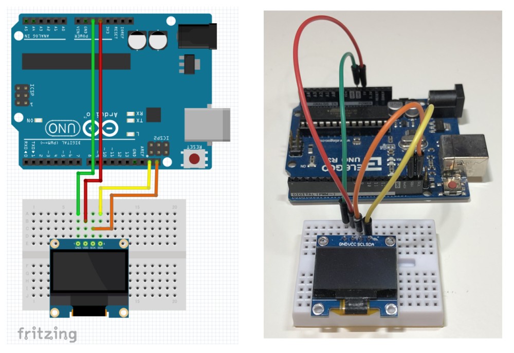
- I2C LCDのfritzing用のデータがインターネットを検索すると見つかりましたので使わさせて頂きました。
- fritzingの回路図(配線図)を基に実際に配線しました。
I2C LCDを使う準備は?
- ライブラリをインストールします
- スケッチを記述する時に必要なI2C LCDデバイスのアドレスを調べます
- 購入したI2C LCDで使えるライブラリがAdfruit社から公開され、Arduino IDEにも登録されていました。[Adafruit SSD1306]と[Adafruit GFX Library]をインストールします。
- I2C LCDデバイスのアドレスを調べるには、Aduinoのウェブで公開されているI2C Scannerを使用します。
// --------------------------------------
// i2c_scanner
//
// Version 1
//    This program (or code that looks like it)
//    can be found in many places.
//    For example on the Arduino.cc forum.
//    The original author is not know.
// Version 2, Juni 2012, Using Arduino 1.0.1
//     Adapted to be as simple as possible by Arduino.cc user Krodal
// Version 3, Feb 26  2013
//    V3 by louarnold
// Version 4, March 3, 2013, Using Arduino 1.0.3
//    by Arduino.cc user Krodal.
//    Changes by louarnold removed.
//    Scanning addresses changed from 0...127 to 1...119,
//    according to the i2c scanner by Nick Gammon
//    https://www.gammon.com.au/forum/?id=10896
// Version 5, March 28, 2013
//    As version 4, but address scans now to 127.
//    A sensor seems to use address 120.
// Version 6, November 27, 2015.
//    Added waiting for the Leonardo serial communication.
//
//
// This sketch tests the standard 7-bit addresses
// Devices with higher bit address might not be seen properly.
//

#include <Wire.h>


void setup()
{
  Wire.begin();

  Serial.begin(9600);
  while (!Serial);             // Leonardo: wait for serial monitor
  Serial.println("\nI2C Scanner");
}


void loop()
{
  byte error, address;
  int nDevices;

  Serial.println("Scanning...");

  nDevices = 0;
  for(address = 1; address < 127; address++ )
  {
    // The i2c_scanner uses the return value of
    // the Write.endTransmisstion to see if
    // a device did acknowledge to the address.
    Wire.beginTransmission(address);
    error = Wire.endTransmission();

    if (error == 0)
    {
      Serial.print("I2C device found at address 0x");
      if (address<16)
        Serial.print("0");
      Serial.print(address,HEX);
      Serial.println("  !");

      nDevices++;
    }
    else if (error==4)
    {
      Serial.print("Unknown error at address 0x");
      if (address<16)
        Serial.print("0");
      Serial.println(address,HEX);
    }
  }
  if (nDevices == 0)
    Serial.println("No I2C devices found\n");
  else
    Serial.println("done\n");

  delay(5000);           // wait 5 seconds for next scan
}- I2C Scannerを使うとシリアルモニタにI2C LCDのアドレスが表示されます。IDは”0x3C”であることが解りました。
I2C device found at address 0x3C !I2C LCDのサンプルスケッチを動作させてみる
- I2C LCDに必要なライブラリをインストールすると、同時にLCDの動作を確認できるスケッチのサンプルがインストールされています。
- ファイルメニューから、ファイル ==> スケッチ例 ==> Adfruit SSD1306 ==> ssd1306_128x64_i2c を選びます。
- ssd1306_128x64_i2c のスケッチがArduino IDEに読み出されます。下記の行にI2C LCDのアドレスが記述されています。0x3Dを0x3Cに書き換えて使います。
#define SCREEN_ADDRESS 0x3D ///< See datasheet for Address; 0x3D for 128x64, 0x3C for 128x32- I2C LCDのアドレスは0x3Cに書き換えています。
/**************************************************************************
 This is an example for our Monochrome OLEDs based on SSD1306 drivers

 Pick one up today in the adafruit shop!
 ------> http://www.adafruit.com/category/63_98

 This example is for a 128x64 pixel display using I2C to communicate
 3 pins are required to interface (two I2C and one reset).

 Adafruit invests time and resources providing this open
 source code, please support Adafruit and open-source
 hardware by purchasing products from Adafruit!

 Written by Limor Fried/Ladyada for Adafruit Industries,
 with contributions from the open source community.
 BSD license, check license.txt for more information
 All text above, and the splash screen below must be
 included in any redistribution.
 **************************************************************************/

#include <SPI.h>
#include <Wire.h>
#include <Adafruit_GFX.h>
#include <Adafruit_SSD1306.h>

#define SCREEN_WIDTH 128 // OLED display width, in pixels
#define SCREEN_HEIGHT 64 // OLED display height, in pixels

// Declaration for an SSD1306 display connected to I2C (SDA, SCL pins)
// The pins for I2C are defined by the Wire-library.
// On an arduino UNO:       A4(SDA), A5(SCL)
// On an arduino MEGA 2560: 20(SDA), 21(SCL)
// On an arduino LEONARDO:   2(SDA),  3(SCL), ...
#define OLED_RESET     -1 // Reset pin # (or -1 if sharing Arduino reset pin)
#define SCREEN_ADDRESS 0x3C ///< See datasheet for Address; 0x3D for 128x64, 0x3C for 128x32
Adafruit_SSD1306 display(SCREEN_WIDTH, SCREEN_HEIGHT, &Wire, OLED_RESET);

#define NUMFLAKES     10 // Number of snowflakes in the animation example

#define LOGO_HEIGHT   16
#define LOGO_WIDTH    16
static const unsigned char PROGMEM logo_bmp[] =
{ 0b00000000, 0b11000000,
  0b00000001, 0b11000000,
  0b00000001, 0b11000000,
  0b00000011, 0b11100000,
  0b11110011, 0b11100000,
  0b11111110, 0b11111000,
  0b01111110, 0b11111111,
  0b00110011, 0b10011111,
  0b00011111, 0b11111100,
  0b00001101, 0b01110000,
  0b00011011, 0b10100000,
  0b00111111, 0b11100000,
  0b00111111, 0b11110000,
  0b01111100, 0b11110000,
  0b01110000, 0b01110000,
  0b00000000, 0b00110000 };

void setup() {
  Serial.begin(9600);

  // SSD1306_SWITCHCAPVCC = generate display voltage from 3.3V internally
  if(!display.begin(SSD1306_SWITCHCAPVCC, SCREEN_ADDRESS)) {
    Serial.println(F("SSD1306 allocation failed"));
    for(;;); // Don't proceed, loop forever
  }

  // Show initial display buffer contents on the screen --
  // the library initializes this with an Adafruit splash screen.
  display.display();
  delay(2000); // Pause for 2 seconds

  // Clear the buffer
  display.clearDisplay();

  // Draw a single pixel in white
  display.drawPixel(10, 10, SSD1306_WHITE);

  // Show the display buffer on the screen. You MUST call display() after
  // drawing commands to make them visible on screen!
  display.display();
  delay(2000);
  // display.display() is NOT necessary after every single drawing command,
  // unless that's what you want...rather, you can batch up a bunch of
  // drawing operations and then update the screen all at once by calling
  // display.display(). These examples demonstrate both approaches...

  testdrawline();      // Draw many lines

  testdrawrect();      // Draw rectangles (outlines)

  testfillrect();      // Draw rectangles (filled)

  testdrawcircle();    // Draw circles (outlines)

  testfillcircle();    // Draw circles (filled)

  testdrawroundrect(); // Draw rounded rectangles (outlines)

  testfillroundrect(); // Draw rounded rectangles (filled)

  testdrawtriangle();  // Draw triangles (outlines)

  testfilltriangle();  // Draw triangles (filled)

  testdrawchar();      // Draw characters of the default font

  testdrawstyles();    // Draw 'stylized' characters

  testscrolltext();    // Draw scrolling text

  testdrawbitmap();    // Draw a small bitmap image

  // Invert and restore display, pausing in-between
  display.invertDisplay(true);
  delay(1000);
  display.invertDisplay(false);
  delay(1000);

  testanimate(logo_bmp, LOGO_WIDTH, LOGO_HEIGHT); // Animate bitmaps
}

void loop() {
}

void testdrawline() {
  int16_t i;

  display.clearDisplay(); // Clear display buffer

  for(i=0; i<display.width(); i+=4) {
    display.drawLine(0, 0, i, display.height()-1, SSD1306_WHITE);
    display.display(); // Update screen with each newly-drawn line
    delay(1);
  }
  for(i=0; i<display.height(); i+=4) {
    display.drawLine(0, 0, display.width()-1, i, SSD1306_WHITE);
    display.display();
    delay(1);
  }
  delay(250);

  display.clearDisplay();

  for(i=0; i<display.width(); i+=4) {
    display.drawLine(0, display.height()-1, i, 0, SSD1306_WHITE);
    display.display();
    delay(1);
  }
  for(i=display.height()-1; i>=0; i-=4) {
    display.drawLine(0, display.height()-1, display.width()-1, i, SSD1306_WHITE);
    display.display();
    delay(1);
  }
  delay(250);

  display.clearDisplay();

  for(i=display.width()-1; i>=0; i-=4) {
    display.drawLine(display.width()-1, display.height()-1, i, 0, SSD1306_WHITE);
    display.display();
    delay(1);
  }
  for(i=display.height()-1; i>=0; i-=4) {
    display.drawLine(display.width()-1, display.height()-1, 0, i, SSD1306_WHITE);
    display.display();
    delay(1);
  }
  delay(250);

  display.clearDisplay();

  for(i=0; i<display.height(); i+=4) {
    display.drawLine(display.width()-1, 0, 0, i, SSD1306_WHITE);
    display.display();
    delay(1);
  }
  for(i=0; i<display.width(); i+=4) {
    display.drawLine(display.width()-1, 0, i, display.height()-1, SSD1306_WHITE);
    display.display();
    delay(1);
  }

  delay(2000); // Pause for 2 seconds
}

void testdrawrect(void) {
  display.clearDisplay();

  for(int16_t i=0; i<display.height()/2; i+=2) {
    display.drawRect(i, i, display.width()-2*i, display.height()-2*i, SSD1306_WHITE);
    display.display(); // Update screen with each newly-drawn rectangle
    delay(1);
  }

  delay(2000);
}

void testfillrect(void) {
  display.clearDisplay();

  for(int16_t i=0; i<display.height()/2; i+=3) {
    // The INVERSE color is used so rectangles alternate white/black
    display.fillRect(i, i, display.width()-i*2, display.height()-i*2, SSD1306_INVERSE);
    display.display(); // Update screen with each newly-drawn rectangle
    delay(1);
  }

  delay(2000);
}

void testdrawcircle(void) {
  display.clearDisplay();

  for(int16_t i=0; i<max(display.width(),display.height())/2; i+=2) {
    display.drawCircle(display.width()/2, display.height()/2, i, SSD1306_WHITE);
    display.display();
    delay(1);
  }

  delay(2000);
}

void testfillcircle(void) {
  display.clearDisplay();

  for(int16_t i=max(display.width(),display.height())/2; i>0; i-=3) {
    // The INVERSE color is used so circles alternate white/black
    display.fillCircle(display.width() / 2, display.height() / 2, i, SSD1306_INVERSE);
    display.display(); // Update screen with each newly-drawn circle
    delay(1);
  }

  delay(2000);
}

void testdrawroundrect(void) {
  display.clearDisplay();

  for(int16_t i=0; i<display.height()/2-2; i+=2) {
    display.drawRoundRect(i, i, display.width()-2*i, display.height()-2*i,
      display.height()/4, SSD1306_WHITE);
    display.display();
    delay(1);
  }

  delay(2000);
}

void testfillroundrect(void) {
  display.clearDisplay();

  for(int16_t i=0; i<display.height()/2-2; i+=2) {
    // The INVERSE color is used so round-rects alternate white/black
    display.fillRoundRect(i, i, display.width()-2*i, display.height()-2*i,
      display.height()/4, SSD1306_INVERSE);
    display.display();
    delay(1);
  }

  delay(2000);
}

void testdrawtriangle(void) {
  display.clearDisplay();

  for(int16_t i=0; i<max(display.width(),display.height())/2; i+=5) {
    display.drawTriangle(
      display.width()/2  , display.height()/2-i,
      display.width()/2-i, display.height()/2+i,
      display.width()/2+i, display.height()/2+i, SSD1306_WHITE);
    display.display();
    delay(1);
  }

  delay(2000);
}

void testfilltriangle(void) {
  display.clearDisplay();

  for(int16_t i=max(display.width(),display.height())/2; i>0; i-=5) {
    // The INVERSE color is used so triangles alternate white/black
    display.fillTriangle(
      display.width()/2  , display.height()/2-i,
      display.width()/2-i, display.height()/2+i,
      display.width()/2+i, display.height()/2+i, SSD1306_INVERSE);
    display.display();
    delay(1);
  }

  delay(2000);
}

void testdrawchar(void) {
  display.clearDisplay();

  display.setTextSize(1);      // Normal 1:1 pixel scale
  display.setTextColor(SSD1306_WHITE); // Draw white text
  display.setCursor(0, 0);     // Start at top-left corner
  display.cp437(true);         // Use full 256 char 'Code Page 437' font

  // Not all the characters will fit on the display. This is normal.
  // Library will draw what it can and the rest will be clipped.
  for(int16_t i=0; i<256; i++) {
    if(i == '\n') display.write(' ');
    else          display.write(i);
  }

  display.display();
  delay(2000);
}

void testdrawstyles(void) {
  display.clearDisplay();

  display.setTextSize(1);             // Normal 1:1 pixel scale
  display.setTextColor(SSD1306_WHITE);        // Draw white text
  display.setCursor(0,0);             // Start at top-left corner
  display.println(F("Hello, world!"));

  display.setTextColor(SSD1306_BLACK, SSD1306_WHITE); // Draw 'inverse' text
  display.println(3.141592);

  display.setTextSize(2);             // Draw 2X-scale text
  display.setTextColor(SSD1306_WHITE);
  display.print(F("0x")); display.println(0xDEADBEEF, HEX);

  display.display();
  delay(2000);
}

void testscrolltext(void) {
  display.clearDisplay();

  display.setTextSize(2); // Draw 2X-scale text
  display.setTextColor(SSD1306_WHITE);
  display.setCursor(10, 0);
  display.println(F("scroll"));
  display.display();      // Show initial text
  delay(100);

  // Scroll in various directions, pausing in-between:
  display.startscrollright(0x00, 0x0F);
  delay(2000);
  display.stopscroll();
  delay(1000);
  display.startscrollleft(0x00, 0x0F);
  delay(2000);
  display.stopscroll();
  delay(1000);
  display.startscrolldiagright(0x00, 0x07);
  delay(2000);
  display.startscrolldiagleft(0x00, 0x07);
  delay(2000);
  display.stopscroll();
  delay(1000);
}

void testdrawbitmap(void) {
  display.clearDisplay();

  display.drawBitmap(
    (display.width()  - LOGO_WIDTH ) / 2,
    (display.height() - LOGO_HEIGHT) / 2,
    logo_bmp, LOGO_WIDTH, LOGO_HEIGHT, 1);
  display.display();
  delay(1000);
}

#define XPOS   0 // Indexes into the 'icons' array in function below
#define YPOS   1
#define DELTAY 2

void testanimate(const uint8_t *bitmap, uint8_t w, uint8_t h) {
  int8_t f, icons[NUMFLAKES][3];

  // Initialize 'snowflake' positions
  for(f=0; f< NUMFLAKES; f++) {
    icons[f][XPOS]   = random(1 - LOGO_WIDTH, display.width());
    icons[f][YPOS]   = -LOGO_HEIGHT;
    icons[f][DELTAY] = random(1, 6);
    Serial.print(F("x: "));
    Serial.print(icons[f][XPOS], DEC);
    Serial.print(F(" y: "));
    Serial.print(icons[f][YPOS], DEC);
    Serial.print(F(" dy: "));
    Serial.println(icons[f][DELTAY], DEC);
  }

  for(;;) { // Loop forever...
    display.clearDisplay(); // Clear the display buffer

    // Draw each snowflake:
    for(f=0; f< NUMFLAKES; f++) {
      display.drawBitmap(icons[f][XPOS], icons[f][YPOS], bitmap, w, h, SSD1306_WHITE);
    }

    display.display(); // Show the display buffer on the screen
    delay(200);        // Pause for 1/10 second

    // Then update coordinates of each flake...
    for(f=0; f< NUMFLAKES; f++) {
      icons[f][YPOS] += icons[f][DELTAY];
      // If snowflake is off the bottom of the screen...
      if (icons[f][YPOS] >= display.height()) {
        // Reinitialize to a random position, just off the top
        icons[f][XPOS]   = random(1 - LOGO_WIDTH, display.width());
        icons[f][YPOS]   = -LOGO_HEIGHT;
        icons[f][DELTAY] = random(1, 6);
      }
    }
  }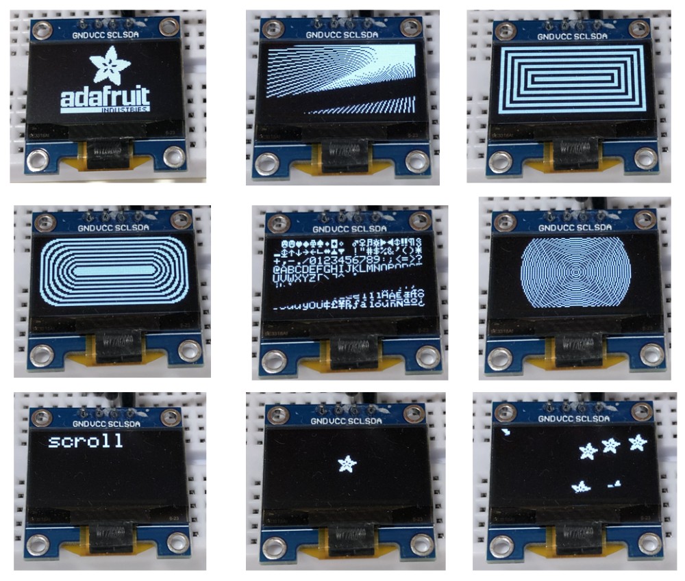
}- スケッチをコンパイルしてArduinoに書き込むとLCDに図形や文字が表示されます。色々な表示方法で図形や文字が画面に現れるのに驚きました。
- 一部画像が欠けていますが、これは画像のトレースとカメラのシャッタースピードの関係でこのように写ります。肉眼で見るときれいに見えます。
I2C LCDの座標は?
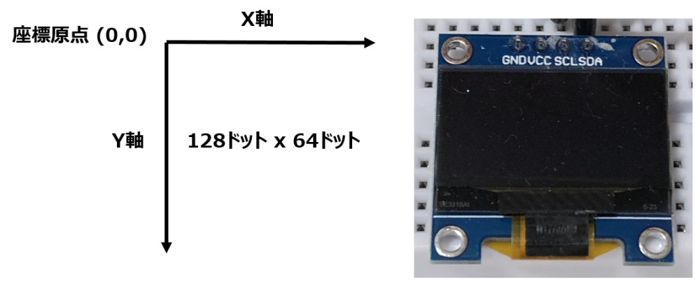
- I2C LCDの座標は、左上の角を(0,0)として、横がX、縦がYになります。
L2C LCDに描画するスケッチの構成は?
- サンプルスケッチ (ssd1306_128x64_i2c)を参照しながら、I2C LCDの初期設定を探します。
- 必要なライブラリです。
#include <Wire.h>
#include <Adafruit_GFX.h>
#include <Adafruit_SSD1306.h>- 購入したLCDスクリーンは 128 x 64 なので、幅と縦の大きさを128と64に設定します。
#define SCREEN_WIDTH 128 // OLED display width, in pixels
#define SCREEN_HEIGHT 64 // OLED display height, in pixels - I2C LCDのリセットの設定です。Arduinoのリセットピンとの兼用の場合は -1にします。
#define OLED_RESET -1 // Reset pin # (or -1 if sharing Arduino reset pin)- I2C LCDのアドレスを設定します。アドレスを 0x3Cとします。(何故か128×64は0x3Dと書かれています?)
#define SCREEN_ADDRESS 0x3C ///< See datasheet for Address; 0x3D for 128x64, 0x3C for 128x32- I2C LCDの設定を行います。
Adafruit_SSD1306 display(SCREEN_WIDTH, SCREEN_HEIGHT, &Wire, OLED_RESET);- サンプルスケッチ (ssd1306_128x64_i2c)を参照しながら、setup(), loop()に必要な記述を探します。
- 描画前にはdisplay.clearDisplay()でバッファをクリアして、描画の設定ができたらdisplay.display()で描画します。
display.clearDisplay();
display.display();
I2C LCDに文字を描くスケッチは?
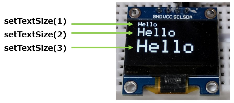
- 文字サイズの指定にはをdisplay.setTextSize(1)を使います。サイズは”1″が10ピクセル、”2″が20ピクセル…となります。
- 色指定はdisplay.setTextColor(SSD1306_WHITE)を使います。白黒LCDなのでWHITEにします。
- 位置指定はdisplay.setCursor(0, 0)を使います。X,Y座標を入力します。
- 文字の出力はdisplay.println()を使います。文字は””で囲みます。サンプルスケッチではF()が使われていました。F()はArduino IDEのマクロで、FlashROMデータを活用することでSRAMで使用できるの領域を広げることが出来るようです。
// I2C LCDに文字を表示する

#include <Wire.h>
#include <Adafruit_GFX.h>
#include <Adafruit_SSD1306.h>

#define SCREEN_WIDTH 128 // OLED display width, in pixels
#define SCREEN_HEIGHT 64 // OLED display height, in pixels

#define OLED_RESET     -1 // Reset pin # (or -1 if sharing Arduino reset pin)
#define SCREEN_ADDRESS 0x3C ///< See datasheet for Address; 0x3D for 128x64, 0x3C for 128x32
Adafruit_SSD1306 display(SCREEN_WIDTH, SCREEN_HEIGHT, &Wire, OLED_RESET);

void setup() {
  Serial.begin(9600);

  // SSD1306_SWITCHCAPVCC = generate display voltage from 3.3V internally
  if(!display.begin(SSD1306_SWITCHCAPVCC, SCREEN_ADDRESS)) {
    Serial.println(F("SSD1306 allocation failed"));
    for(;;); // Don't proceed, loop forever
  }

  display.clearDisplay();

  display.setTextSize(1); // Draw 1X-scale text
  display.setTextColor(SSD1306_WHITE);
  display.setCursor(10, 0);
  display.println(F("Hello"));

  display.setTextSize(2); // Draw 2X-scale text
  display.setCursor(10, 10);
  display.println(F("Hello"));

  display.setTextSize(3); // Draw 3X-scale text
  display.setCursor(10, 30);
  display.println(F("Hello"));

  display.display();

}

void loop() {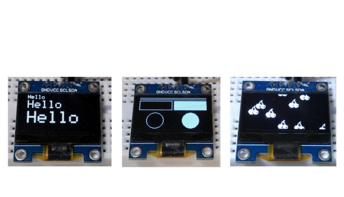
}- ”Hello”をサイズを1(10ピクセル), 2(20ピクセル), 3(30ピクセル)と変えて表示しました。
- 表示位置を端から10ピクセル右にしています。
I2C LCDに線、四角形、円を描くスケッチは?
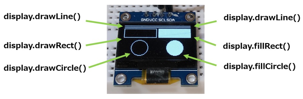
- 線を描くには、display.drawLine(X0,Y0,X1,Y1, SSD1306_WHITE) を使います。X0,Y0は開始位置、X1,Y1は終端位置です。SSD1306_WHITEは白色を指定しています。
- 四角形を描くのは、display.drawRect(X0,Y0,X1,Y1, SSD1306_WHITE)を使います。X0,Y0は開始位置、X1,Y1は開始位置からの相対距離です。SSD1306_WHITEは白色を指定しています。
- 円を描くのは、display.drawCircle(X0,Y0,r,SSD1306_WHITE)を使います。X0,Y0は円の中心、rは半径です。SSD1306_WHITEは白色を指定しています。
- 4角形と円の内部を白色で埋めるときは、fillRect()関数、fillCircle()関数を使います。
- この他、角の丸い四角形、三角形を描く関数もあります。サンプルスケッチ (ssd1306_128x64_i2c)を調べると表記方法が解ります。
// I2C LCDに図形を描画する

#include <Wire.h>
#include <Adafruit_GFX.h>
#include <Adafruit_SSD1306.h>

#define SCREEN_WIDTH 128 // OLED display width, in pixels
#define SCREEN_HEIGHT 64 // OLED display height, in pixels

#define OLED_RESET     -1 // Reset pin # (or -1 if sharing Arduino reset pin)
#define SCREEN_ADDRESS 0x3C ///< See datasheet for Address; 0x3D for 128x64, 0x3C for 128x32
Adafruit_SSD1306 display(SCREEN_WIDTH, SCREEN_HEIGHT, &Wire, OLED_RESET);

void setup() {
  Serial.begin(9600);

  // SSD1306_SWITCHCAPVCC = generate display voltage from 3.3V internally
  if(!display.begin(SSD1306_SWITCHCAPVCC, SCREEN_ADDRESS)) {
    Serial.println(F("SSD1306 allocation failed"));
    for(;;); // Don't proceed, loop forever
  }

  display.clearDisplay();

  display.drawLine(3, 3, 125, 3, SSD1306_WHITE);
  display.drawLine(3, 6, 125, 6, SSD1306_WHITE);

  display.drawRect(3, 9, 60, 19, SSD1306_WHITE);
  display.fillRect(66, 9, 60, 19, SSD1306_WHITE);

  display.drawCircle(32, 48, 15, SSD1306_WHITE);
  display.fillCircle(96, 48, 15, SSD1306_WHITE);

  display.display();

}

void loop() {
}- 線、四角形、円を描きました。四角形、円は輪郭を描く関数と内部を塗りつぶす関数使いました。
I2C LCDにビットパタンを描くスケッチは?
- サンプルスケッチ (ssd1306_128x64_i2c)で定義されているビットマップのパターンを 16 x 16 で0を黒、1を白で描くと桜の花びらのようなパターンになります。このパターンをLCDに描いていることが解ります。
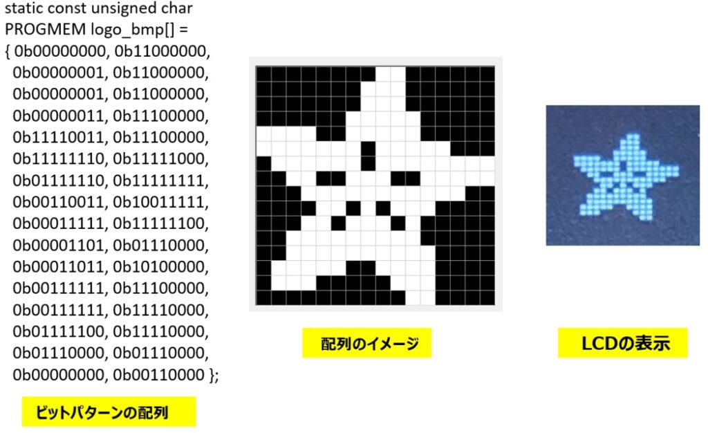
- ビットマップを描くには、display.drawBitmap(X0, Y0, logo_bmp, LOGO_WIDTH, LOGO_HEIGHT, SSD1306_WHITE)を使います。X0,Y0はビットマップの開始座標、logo_bmpはビットマップ配列、ビットマップの幅と高さ、表示色、です。
// I2C LCDにビットパターンの図形を描画する

#include <Wire.h>
#include <Adafruit_GFX.h>
#include <Adafruit_SSD1306.h>

#define SCREEN_WIDTH 128 // OLED display width, in pixels
#define SCREEN_HEIGHT 64 // OLED display height, in pixels

#define OLED_RESET     -1 // Reset pin # (or -1 if sharing Arduino reset pin)
#define SCREEN_ADDRESS 0x3C ///< See datasheet for Address; 0x3D for 128x64, 0x3C for 128x32
Adafruit_SSD1306 display(SCREEN_WIDTH, SCREEN_HEIGHT, &Wire, OLED_RESET);

#define LOGO_HEIGHT   16
#define LOGO_WIDTH    16
static const unsigned char PROGMEM logo_bmp[] =
{ 0b00000000, 0b11000000,
  0b00000001, 0b11000000,
  0b00000001, 0b11000000,
  0b00000011, 0b11100000,
  0b11110011, 0b11100000,
  0b11111110, 0b11111000,
  0b01111110, 0b11111111,
  0b00110011, 0b10011111,
  0b00011111, 0b11111100,
  0b00001101, 0b01110000,
  0b00011011, 0b10100000,
  0b00111111, 0b11100000,
  0b00111111, 0b11110000,
  0b01111100, 0b11110000,
  0b01110000, 0b01110000,
  0b00000000, 0b00110000 };

void setup() {
  Serial.begin(9600);

  // SSD1306_SWITCHCAPVCC = generate display voltage from 3.3V internally
  if(!display.begin(SSD1306_SWITCHCAPVCC, SCREEN_ADDRESS)) {
    Serial.println(F("SSD1306 allocation failed"));
    for(;;); // Don't proceed, loop forever
  }

  display.clearDisplay();

  display.drawBitmap(62,32,logo_bmp, LOGO_WIDTH, LOGO_HEIGHT, SSD1306_WHITE);

  display.display();
  delay(1000);

}

void loop() {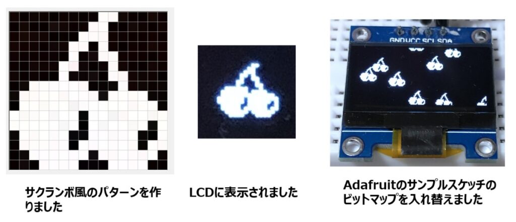
}- サクランボ風の16×16のパターンを作成しました。このパターンを基に配列データを作成し、LCDに表示させました。
- Adafruitのサンプルスケッチのデータを置き換えると、サクランボが降ってくるような画像に変わりました。
// I2C LCDにサクランボ風のビットパターンの図形を描画する

#include <Wire.h>
#include <Adafruit_GFX.h>
#include <Adafruit_SSD1306.h>

#define SCREEN_WIDTH 128 // OLED display width, in pixels
#define SCREEN_HEIGHT 64 // OLED display height, in pixels

#define OLED_RESET     -1 // Reset pin # (or -1 if sharing Arduino reset pin)
#define SCREEN_ADDRESS 0x3C ///< See datasheet for Address; 0x3D for 128x64, 0x3C for 128x32
Adafruit_SSD1306 display(SCREEN_WIDTH, SCREEN_HEIGHT, &Wire, OLED_RESET);

#define LOGO_HEIGHT   16
#define LOGO_WIDTH    16
static const unsigned char PROGMEM logo_bmp[] =
{ 0b00000000, 0b01100000,
  0b00000000, 0b11000000,
  0b00000001, 0b11000000,
  0b00000011, 0b01000000,
  0b00000010, 0b01100000,
  0b00000110, 0b00100000,
  0b00000100, 0b00110000,
  0b00111111, 0b00010000,
  0b01111111, 0b01111000,
  0b01111111, 0b11111110,
  0b11111110, 0b11111111,
  0b11111110, 0b11111101,
  0b01111100, 0b11111001,
  0b01111101, 0b11111011,
  0b00111111, 0b01111110,
  0b00011110, 0b00111100 };

void setup() {
  Serial.begin(9600);

  // SSD1306_SWITCHCAPVCC = generate display voltage from 3.3V internally
  if(!display.begin(SSD1306_SWITCHCAPVCC, SCREEN_ADDRESS)) {
    Serial.println(F("SSD1306 allocation failed"));
    for(;;); // Don't proceed, loop forever
  }

  display.clearDisplay();

  display.drawBitmap(62,32,logo_bmp, LOGO_WIDTH, LOGO_HEIGHT, SSD1306_WHITE);

  display.display();
  delay(1000);

}

void loop() {
}
I2C LCD の使用感と応用は?
- 実際に文字や図形を描いてみると、思ったより簡単にスケッチで操作できることがわかりました。ライブラリを作成されたAdafruit社さんに感謝です。
- LCD I2Cインターフェースで接続されているので、4本の線を配線するだけで動作するのも魅力です。
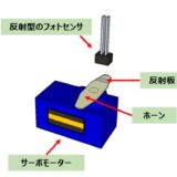
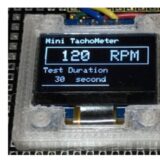
- サーボモータの回転数をArduinoの割り込み関数を使って計測する簡単なタコメータを作成しました。計測値はシリアルモニタでPCの画面で表示させましたが、携帯性に欠けるので、I2C LCDを簡易タコメータに接続し、測定した回転数を表示させました。
タコメータにI2C LCDを表示させた記事は?
まとめ
- I2C LCD は配線が簡単で簡単に画像の表示ができました。使うときは最初にI2Cアドレスをスキャナで確認してスケッチを書けば問題なく動くと思います。PCのシリアルモニタでデータの確認はできますが、状況によってはLCDの表示が便利な場面もあると思います。
ご質問、誤植の指摘などありましたら。「問い合わせ 」のページからお願いします。